BCA 4TH SEM COMPUTER NETWORK
UNIT -1
DATA COMMUNICATION
Q.1 Simple Definition of communication.
Data communications are the exchange of data between two devices via some form of transmission medium such as a wire cable. For data communications to occur, the communicating devices must be part of a communication system made up of a combination of hardware (physical equipment) and software (programs).
The effectiveness of a data communications system depends on four fundamental characteristics:
delivery,accuracy, timeliness, and jitter.
I. Delivery. The system must deliver data to
the correct destination. Data must be received by the intended device or user
and only by that device or user.
2. Accuracy. The system must deliver the data
accurately. Data that have been altered in transmission and left uncorrected
are unusable.
3. Timeliness. The system must deliver data in
a timely manner. Data delivered late are useless. In the case of video and
audio, timely delivery means delivering data as they are produced, in the same
order that they are produced, and without significant delay. This kind of
delivery is called real-time transmission.
4. Jitter. Jitter refers to the variation in
the packet arrival time. It is the uneven delay in the delivery of audio or
video packets. For example, let us assume that video packets are sent every 3D
ms. If some of the packets arrive with 3D-ms delay and others with 4D-ms delay,
an uneven quality in the video is the result.
Q.2 Explain the five components of Data Communication System?
The five components are :
1. Message - It is the information to be communicated. Popular forms of
information include text, pictures, audio, video etc. Text is converted to
binary, number doesnt converted, image is converted to pixels, etc.
2. Sender - It is the device which sends the data messages. It can be a
computer, workstation, telephone handset etc.
3. Receiver - It is the device which receives the data messages. It can
be a computer, workstation, telephone handset etc.
4. Transmission Medium - It is the physical path by which a message
travels from sender to receiver. Some examples include twisted-pair wire,
coaxial cable, radio waves etc.
5. Protocol - It is a set of rules that governs the data communications.
It represents an agreement between the communicating devices. Without a
protocol, two devices may be connected but not communicating.
Q.3 What is a Network?
A network consists of two or more computers that are linked in order to share resources (such as printers and CDs), exchange files, or allow electronic communications. The computers on a network may be linked through cables, telephone lines, radio waves, satellites, or infrared light beams.
Local Area Network
A Local Area Network (LAN) is a network that is confined to a relatively small area. It is generally limited to a geographic area such as a writing lab, school, or building.
Computers connected to a network are broadly categorized as servers or workstations. Servers are generally not used by humans directly, but rather run continuously to provide "services" to the other computers (and their human users) on the network. Services provided can include printing and faxing, software hosting, file storage and sharing, messaging, data storage and retrieval, complete access control (security) for the network's resources, and many others.
Wide Area Network
Wide Area Networks (WANs) connect networks in larger geographic areas, such as Florida, the United States, or the world. Dedicated transoceanic cabling or satellite uplinks may be used to connect this type of global network.
Q.4 Why we need computer networks? Need for Computer Networking
Computer networks help users on the network to share the resources and in communication. Can you imagine a world now without emails, online newspapers, blogs, chat and the other services offered by the internet?
The following are the important uses and benefits of a computer network.
File sharing: Networking of computers helps the network users to share data files.

Hardware sharing: Users can share devices such as printers, scanners, CD-ROM drives, hard drives etc. Without computer networks, device sharing is not possible.

Application sharing: Applications can be shared over the network, and this allows to implement client/server applications
User communication: Networks allow users to communicate using e-mail, newsgroups, and video conferencing etc.

Network gaming: A lot of network games are available, which allow multi-users to play from different locations.
Voice over IP (VoIP): Voice over Internet Protocol (IP) is a revolutionary change in telecommunication which allows to send telephone calls (voice data) using standard Internet Protocol (IP) rather than by traditional PSTN.
Q.5 Protocol
In information technology, a protocol is the special set of rules that end points in a telecommunication connection use when they communicate. Protocols specify interactions between the communicating entities.
Protocols exist at several levels in a telecommunication connection. For example, there are protocols for the data interchange at the hardware device level and protocols for data interchange at the application program level. In the standard model known as Open Systems Interconnection (OSI), there are one or more protocols at each layer in the telecommunication exchange that both ends of the exchange must recognize and observe. Protocols are often described in an industry or international standard.
The TCP/IP Internet protocols, a common example, consist of:
· Transmission Control Protocol (TCP), which uses a set of rules to exchange messages with other Internet points at the information packet level
· Internet Protocol (IP), which uses a set of rules to send and receive messages at the Internet address level
· Additional protocols that include the Hypertext Transfer Protocol (HTTP) and File Transfer Protocol (FTP), each with defined sets of rules to use with corresponding programs elsewhere on the Internet
There are many other Internet protocols, such as the Border Gateway Protocol (BGP) and the Dynamic Host Configuration Protocol (DHCP).
Q.6 What are Standards?
The standards are the documents that contain technical and physical specifications about the network being designed. The networks can be reliable and efficient by following certain standards.
Types of network standards
The two types of network standards are as follows:
1. De facto standard
2. De jure standard
1. de facto
De facto means by tradition or by facts. These standards are developed without any formal planning. These standards come into existence due to historical developments. These standards are still being used by many organizations in the world. SNA is an example of de facto standard
2. De Jure
De jure means according to law or regulation. These standards are developed with proper research to fulfill the requirement of data communication. The major organization to develop communication protocols and standards are as follows:
1. American national standard institute (ANSI)
2. Institute of electrical and electronics engineers (IEEE)
3. International standard organization (ISO)
4. International telecommunications union – telecommunication standards sector (itu-t)
5. The electronic industries association (EIA)
6. Telcordia
What is network topology? Write the names of topologies.
A network can be configured or arranged in different ways. The physical layout or arrangement of connected devices in a network is called topology. It is the shape of a network. Different network topologies are as follows:
1. Bus topology
2. Ring topology
3. Star topology
4. Tree topology
5. Mesh topology
What is bus topology? Explain its working with diagram. Discuss its advantages and disadvantages.
Bus topology is the simplest type of network. It supports a small number of computers in bus topology, all computers or network nodes are connected to a common communication medium. This medium is often a central wire known as bus. The terminators are used at the end of a bus to absorb signals. A collision can occur in bus topology if two computers transmit data at same time. Bus topology is mostly used in peer-to peer networks.
Working of bus network
 The sending computer sends the data and
destination address through the bus. The data and address move from one
computer to the other in the network. Each computer checks the address. If it
matches with the address of a computer. The computer keeps the data. Otherwise
the data moves to the next computer.
The sending computer sends the data and
destination address through the bus. The data and address move from one
computer to the other in the network. Each computer checks the address. If it
matches with the address of a computer. The computer keeps the data. Otherwise
the data moves to the next computer.
Advantages
1. It is simple and easy to use.
2. It requires small length of cable to connect computers.
3. It is less expensive.
4. It is easy to extend a bus. It allows more computers to join network.
5. If one node fails, it does not affect the rest of the network.
Disadvantages
1. It is difficult to troubleshoot.
2. It only supports small number of computers.
3. The network speed slows down as the number of computers increases.
Ring network
A ring network is a network topology in which each node connects to exactly two other nodes, forming a single continuous pathway for signals through each node - a ring. Data travel from node to node, with each node along the way handling every packet.
Rings can be unidirectional, with all traffic travelling either clockwise or anticlockwise around the ring, or bidirectional (as in SONET/SDH). Because a unidirectional ring topology provides only one pathway between any two nodes, unidirectional ring networks may be disrupted by the failure of a single link.[1] A node failure or cable break might isolate every node attached to the ring. In response, some ring networks add a "counter-rotating ring" (C-Ring) to form a redundant topology

Advantages
· Very orderly network where every device has access to the token and the opportunity to transmit
· Performs better than a bus topology under heavy network load
· Does not require a central node to manage the connectivity between the computers
· Due to the point to point line configuration of devices with a device on either side (each device is connected to its immediate neighbor), it is quite easy to install and reconfigure since adding or removing a device requires moving just two connections.
· Point to point line configuration makes it easy to identify and isolate faults.
· Reconfiguration for line faults of bidirectional rings can be very fast, as switching happens at a high level, and thus the traffic does not require individual rerouting
Disadvantages
· One malfunctioning workstation can create problems for the entire network. This can be solved by using a dual ring or a switch that closes off the break.
· Moving, adding and changing the devices can affect the network
· Communication delay is directly proportional to number of nodes in the network
· Bandwidth is shared on all links between devices
· More difficult to configure than a Star: node adjunction = Ring shutdown and reconfiguration
·
What is Star topology?
In Star topology, all the
components of network are connected to the central device called “hub” which
may be a hub, a router or a switch. Unlike Bus topology(discussed
earlier), where nodes were connected to central cable, here all the
workstations are connected to central device with a point-to-point connection.
So it can be said that every computer is indirectly connected to every other
node by the help of “hub”.
All the data on the star topology passes through
the central device before reaching the intended destination. Hub acts as a
junction to connect different nodes present in Star Network, and at the same
time it manages and controls whole of the network. Depending on which central
device is used, “hub” can act as repeater or signal booster. Central device can
also communicate with other hubs of different network. Unshielded Twisted Pair
(UTP) Ethernet cable is used to connect workstations to central node.
|
|
|
Star Topology Diagram |

· Advantages of Star Topology
·
1) As
compared to Bus topology it gives far much better performance, signals don’t
necessarily get transmitted to all the workstations. A sent signal reaches the
intended destination after passing through no more than 3-4 devices and 2-3
links. Performance of the network is dependent on the capacity of central hub.
2) Easy to connect new nodes or devices. In star
topology new nodes can be added easily without affecting rest of the network.
Similarly components can also be removed easily.
3) Centralized management. It helps in monitoring
the network.
4) Failure of one node or link doesn’t affect the
rest of network. At the same time its easy to detect the failure and
troubleshoot it.
· Disadvantages of Star Topology
·
1) Too much dependency on central device has its own
drawbacks. If it fails whole network goes down.
2)
The use of hub, a router or a switch as central device increases the overall
cost of the network.
3) Performance and as well number of nodes which
can be added in such topology is depended on capacity of central device.
What is Tree Topology?
Tree Topology integrates the characteristics of
Star and Bus
Topology. Earlier we saw how in Physical Star network
Topology, computers (nodes) are connected by each other
through central hub. And we also saw in Bus Topology, work station devices are
connected by the common cable called Bus. After understanding these two network
configurations, we can understand tree topology better. In Tree Topology, the
number of Star networks are connected using Bus. This main cable seems like a
main stem of a tree, and other star networks as the branches. It is also called Expanded Star Topology. Ethernet protocol is commonly used in this type of
topology. The diagram below will make it clear.
|
|
|
Tree Topology |

Let’s discuss the advantages and disadvantages
of Tree Topology now.
Advantages of Tree Topology
1. It is an
extension of Star and bus Topologies, so in networks where these topologies
can't be implemented individually for reasons related to scalability, tree
topology is the best alternative.
2. Expansion of Network is possible and
easy.
3. Here, we divide the whole network into segments (star
networks), which can be easily managed and maintained.
4. Error detection and correction is easy.
5. Each segment is provided with dedicated point-to-point
wiring to the central hub.
6. If one segment is damaged, other segments are not
affected.
Disadvantages of Tree Topology
1. Because of its basic structure, tree topology, relies
heavily on the main bus cable, if it breaks whole network is crippled.
2. As more and more nodes and segments are added, the
maintenance becomes difficult.
3. Scalability of the network depends on the type of
cable used.
What is Mesh Topology?
In a mesh network
topology, each of the network node, computer and other
devices, are interconnected with one another. Every node not only sends its own
signals but also relays data from other nodes. In fact a true mesh topology is
the one where every node is connected to every other node in the network. This
type of topology is very expensive as there are many redundant connections,
thus it is not mostly used in computer networks. It is commonly used in
wireless networks. Flooding or routing technique is used in mesh topology.
Types of Mesh Network topologies:-
1)Full Mesh Topology:-
|
|
|
Mesh Topology Diagram |

In this, like a
true mesh, each component is connected to every other component. Even after
considering the redundancy factor and cost of this network, its main advantage
is that the network traffic can be redirected to other nodes if one of the
nodes goes down. Full mesh topology is used only for backbone networks.
Transmission Modes in Computer Networks
Transmission mode means transferring of data between two devices. It is also called communication mode. These modes direct the direction of flow of information. There are three types of transmission mode. They are :
· Simplex Mode
· Half duplex Mode
· Full duplex Mode

SIMPLEX Mode
In this type of transmission mode data can be sent only through one direction i.e. communication is unidirectional. We cannot send a message back to the sender. Unidirectional communication is done in Simplex Systems.
Examples of simplex Mode is loudspeaker, television broadcasting, television and remote, keyboard and monitor etc.

HALF DUPLEX Mode
In half duplex system we can send data in both directions but it is done one at a time that is when the sender is sending the data then at that time we can’t send the sender our message. The data is sent in one direction.
Example of half duplex is a walkie- talkie in which message is sent one at a time and messages are sent in both the directions.

FULL DUPLEX Mode
In full duplex system we can send data in both directions as it is bidirectional. Data can be sent in both directions simultaneously. We can send as well as we receive the data.
Example of Full Duplex is a Telephone Network in which there is communication between two persons by a telephone line, through which both can talk and listen at the same time.

In full duplex system there can be two lines one for sending the data and the other for receiving data.

2) Partial Mesh Topology:-
This is far more
practical as compared to full mesh topology. Here, some of the systems are
connected in similar fashion as in mesh topology while rests of the systems are
only connected to 1 or 2 devices. It can be said that in partial mesh, the
workstations are ‘indirectly’ connected to other devices. This one is less
costly and also reduces redundancy.
Advantages of Mesh topology
1) Data can be transmitted from different devices
simultaneously. This topology can withstand high traffic.
2) Even if one of the components fails there is always an
alternative present. So data transfer doesn’t get affected.
3) Expansion and modification in topology can be done
without disrupting other nodes.
Disadvantages of Mesh topology
1) There are high chances of redundancy in many of the
network connections.
2) Overall cost of this network is way too high as
compared to other
network topologies.
3) Set-up and maintenance of this topology is very
difficult. Even administration of the network is tough.
OSI reference model
(Open Systems Interconnection)
OSI (Open Systems Interconnection) is reference model for how applications can communicate over a network. A reference model is a conceptual framework for understanding relationships. The purpose of the OSI reference model is to guide vendors and developers so the digital communication products and software programs they create will interoperate, and to facilitate clear comparisons among communications tools. Most vendors involved in telecommunications make an attempt to describe their products and services in relation to the OSI model. And although useful for guiding discussion and evaluation, OSI is rarely actually implemented, as few network products or standard tools keep all related functions together in well-defined layers as related to the model. The TCP/IP protocols, which define the Internet, do not map cleanly to the OSI model.

Physical (Layer 1)
OSI Model, Layer 1 conveys the bit stream - electrical impulse, light or radio signal — through the network at the electrical and mechanical level. It provides the hardware means of sending and receiving data on a carrier, including defining cables, cards and physical aspects. Fast Ethernet, RS232, and ATM are protocols with physical layer components.
![]() Layer 1 Physical examples include Ethernet, FDDI, B8ZS, V.35,
V.24, RJ45.
Layer 1 Physical examples include Ethernet, FDDI, B8ZS, V.35,
V.24, RJ45.
Data Link (Layer 2)
At OSI Model, Layer 2, data packets are encoded and decoded into bits. It furnishes transmission protocolknowledge and management and handles errors in the physical layer, flow control and frame synchronization. The data link layer is divided into two sub layers: The Media Access Control (MAC) layer and the Logical Link Control (LLC) layer. The MAC sub layer controls how a computer on the network gains access to the data and permission to transmit it. The LLC layer controls frame synchronization, flow control and error checking.
![]() Layer 2 Data Link examples include PPP, FDDI, ATM, IEEE 802.5/
802.2, IEEE 802.3/802.2, HDLC, Frame Relay.
Layer 2 Data Link examples include PPP, FDDI, ATM, IEEE 802.5/
802.2, IEEE 802.3/802.2, HDLC, Frame Relay.
Network (Layer 3)
Layer 3 provides switching and routing technologies, creating logical paths, known as virtual circuits, for transmitting data from node to node. Routing and forwarding are functions of this layer, as well as addressing,internetworking, error handling, congestion control and packet sequencing.
![]() Layer 3 Network examples include AppleTalk DDP, IP, IPX.
Layer 3 Network examples include AppleTalk DDP, IP, IPX.
Transport (Layer 4)
OSI Model, Layer 4, provides transparent transfer of data between end systems, or hosts, and is responsible for end-to-end error recovery and flow control. It ensures complete data transfer.
![]() Layer 4 Transport examples include SPX, TCP, UDP.
Layer 4 Transport examples include SPX, TCP, UDP.
Session (Layer 5)
This layer establishes, manages and terminates connections between applications. The session layer sets up, coordinates, and terminates conversations, exchanges, and dialogues between the applications at each end. It deals with session and connection coordination.
![]() Layer 5 Session examples include NFS, NetBios names, RPC, SQL.
Layer 5 Session examples include NFS, NetBios names, RPC, SQL.
Presentation (Layer 6)
This layer provides independence from differences in data representation (e.g., encryption) by translating from application to network format, and vice versa. The presentation layer works to transform data into the form that the application layer can accept. This layer formats and encrypts data to be sent across a network, providing freedom from compatibility problems. It is sometimes called the syntax layer.
![]() Layer 6 Presentation examples include encryption, ASCII, EBCDIC,
TIFF, GIF, PICT, JPEG, MPEG, MIDI.
Layer 6 Presentation examples include encryption, ASCII, EBCDIC,
TIFF, GIF, PICT, JPEG, MPEG, MIDI.
Application (Layer 7)
OSI Model, Layer 7, supports application and end-user processes. Communication partners are identified, quality of service is identified, user authentication and privacy are considered, and any constraints on datasyntax are identified. Everything at this layer is application-specific. This layer provides application services forfile transfers, e-mail, and other network software services. Telnet and FTP are applications that exist entirely in the application level. Tiered application architectures are part of this layer.
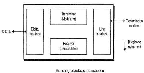
MODEM

Modem is abbreviation for Modulator – Demodulator. Modems are used for data transfer from one computernetwork to another computer network through telephone lines. The computer network works in digital mode, while analog technology is used for carrying massages across phone lines.
Modulator converts information from digital mode to analog mode at the transmitting end and demodulatorconverts the same from analog to digital at receiving end. The process of converting analog signals of one computer network into digital signals of another computer network so they can be processed by a receiving computer is referred to as digitizing.
When an analog facility is used for data communication between two digital devices called Data Terminal Equipment (DTE), modems are used at each end. DTE can be a terminal or a computer.
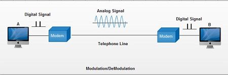
The modem at the transmitting end converts the digital signal generated by DTE into an analog signal by modulating a carrier. This modem at the receiving end demodulates the carrier and hand over the demodulated digital signal to the DTE.
The transmission medium between the two modems can be dedicated circuit or a switched telephone circuit. If a switched telephone circuit is used, then the modems are connected to the local telephone exchanges. Whenever data transmission is required connection between the modems is established through telephone exchanges.
external modem
A stand-alone modem, separate from the computer and connected toit by a serial cable. LEDs on the front of the chassis indicate the current modem status. An external modem can beused with different computers at different times and also with different types of computers.
internal modem
A modem that plugs into an expansion slot within the computer. Unlike an external modem, an internal modemdoes not provide a series of display lights that inform the user of the changing modem states. The user must rely entirely on thecommunications program. Contrast with external modem.
Cable modem
A cable modem is a type of network bridge and modem that provides bi-directional data communication via radio frequency channels on a hybrid fibre-coaxial (HFC) and RFoG infrastructure. Cable modems are primarily used to deliver broadband Internet access in the form of cable Internet, taking advantage of the high bandwidth of a HFC and RFoG network. They are commonly deployed in Australia, Europe,Asia and the Americas.
UNIT 2
TRANSMISSION MEDIA
Q.1 Transmission Mediums in Computer Networks
Data is represented by computers and other telecommunication devices using signals. Signals are transmitted in the form of electromagnetic energy from one device to another. Electromagnetic signals travel through vacuum, air or other transmission mediums to travel between one point to another(from source to receiver).
Electromagnetic energy (includes electrical and magnetic fields) includes power, voice, visible light, radio waves, ultraviolet light, gamma rays etc.
Transmission medium is the means through which we send our data from one place to another. The first layer (physical layer) of Communication Networks OSI Seven layer model is dedicated to the transmission media, we will study the OSI Model later.

Factors to be considered while choosing Transmission Medium
1. Transmission Rate
2. Cost and Ease of Installation
3. Resistance to Environmental Conditions
4. Distances
Bounded/Guided Transmission Media
It is the transmission media in which signals are confined to a specific path using wire or cable. The types of Bounded/ Guided are discussed below.
Twisted Pair Cable
This cable is the most commonly used and is cheaper than others. It is lightweight, cheap, can be installed easily, and they support many different types of network. Some important points :
· Its frequency range is 0 to 3.5 kHz.
· Typical attenuation is 0.2 dB/Km @ 1kHz.
· Typical delay is 50 µs/km.
· Repeater spacing is 2km.
Twisted Pair is of two types :
· Unshielded Twisted Pair (UTP)
· Shielded Twisted Pair (STP)
Unshielded Twisted Pair Cable
It is the most common type of telecommunication when compared with Shielded Twisted Pair Cable which consists of two conductors usually copper, each with its own colour plastic insulator. Identification is the reason behind coloured plastic insulation.
UTP cables consist of 2 or 4 pairs of twisted cable. Cable with 2 pair use RJ-11 connector and 4 pair cable useRJ-45 connector.

Advantages :
Installation is easy
· Flexible
· Cheap
· It has high speed capacity,
· 100 meter limit
· Higher grades of UTP are used in LAN technologies like Ethernet.
It consists of two insulating copper wires (1mm thick). The wires are twisted together in a helical form to reduce electrical interference from similar pair.
Disadvantages :
· Bandwidth is low when compared with Coaxial Cable
· Provides less protection from interference.
Shielded Twisted Pair Cable
This cable has a metal foil or braided-mesh covering which encases each pair of insulated conductors. Electromagnetic noise penetration is prevented by metal casing. Shielding also eliminates crosstalk (explained in KEY TERMS Chapter).
It has same attenuation as unshielded twisted pair. It is faster the unshielded and coaxial cable. It is more expensive than coaxial and unshielded twisted pair.

Advantages :
· Easy to install
· Performance is adequate
· Can be used for Analog or Digital transmission
· Increases the signalling rate
· Higher capacity than unshielded twisted pair
· Eliminates crosstalk
Disadvantages :
· Difficult to manufacture
· Heavy
Coaxial Cable
Coaxial is called by this name because it contains two conductors that are parallel to each other. Copper is used in this as centre conductor which can be a solid wire or a standard one. It is surrounded by PVC installation, a sheath which is encased in an outer conductor of metal foil, barid or both.
Outer metallic wrapping is used as a shield against noise and as the second conductor which completes the circuit. The outer conductor is also encased in an insulating sheath. The outermost part is the plastic cover which protects the whole cable.
Here the most common coaxial standards.
· 50-Ohm RG-7 or RG-11 : used with thick Ethernet.
· 50-Ohm RG-58 : used with thin Ethernet
· 75-Ohm RG-59 : used with cable television
· 93-Ohm RG-62 : used with ARCNET.

There are two types of Coaxial cables :
BaseBand
This is a 50 ohm (Ω) coaxial cable which is used for digital transmission. It is mostly used for LAN’s. Baseband transmits a single signal at a time with very high speed. The major drawback is that it needs amplification after every 1000 feet.
BroadBand
This uses analog transmission on standard cable television cabling. It transmits several simultaneous signal using different frequencies. It covers large area when compared with Baseband Coaxial Cable.
Advantages :
· Bandwidth is high
· Used in long distance telephone lines.
· Transmits digital signals at a very high rate of 10Mbps.
· Much higher noise immunity
· Data transmission without distortion.
· The can span to longer distance at higher speeds as they have better shielding when compared to twisted pair cable
Disadvantages :
· Single cable failure can fail the entire network.
· Difficult to install and expensive when compared with twisted pair.
· If the shield is imperfect, it can lead to grounded loop.
Fiber Optic Cable
These are similar to coaxial cable. It uses electric signals to transmit data. At the centre is the glass core through which light propagates.
In multimode fibres, the core is 50microns, and In single mode fibres, the thickness is 8 to 10 microns.
The core in fiber optic cable is surrounded by glass cladding with lower index of refraction as compared to core to keep all the light in core. This is covered with a thin plastic jacket to protect the cladding. The fibers are grouped together in bundles protected by an outer shield.
Fiber optic cable has bandwidth more than 2 gbps (Gigabytes per Second)

Advantages :
· Provides high quality transmission of signals at very high speed.
· These are not affected by electromagnetic interference, so noise and distortion is very less.
· Used for both analog and digital signals.
Disadvantages :
· It is expensive
· Difficult to install.
· Maintenance is expensive and difficult.
· Do not allow complete routing of light signals.
UnBounded/UnGuided Transmission Media
Unguided or wireless media sends the data through air (or water), which is available to anyone who has a device capable of receiving them. Types of unguided/ unbounded media are discussed below :
· Radio Transmission
· MicroWave Transmission
Radio Transmission
Its frequency is between 10 kHz to 1GHz. It is simple to install and has high attenuation. These waves are used for multicast communications.
Types of Propogation
Radio Transmission utilizes different types of propogation :
· Troposphere : The lowest portion of earth’s atmosphere extending outward approximately 30 miles from the earth’s surface. Clouds, jet planes, wind is found here.
· Ionosphere : The layer of the atmosphere above troposphere, but below space. Contains electrically charged particles.
Microwave Transmission
It travels at high frequency than the radio waves. It requires the sender to be inside of the receiver. It operates in a system with a low gigahertz range. It is mostly used for unicast communication.
There are 2 types of Microwave Transmission :
1. Terrestrial Microwave
2. Satellite Microwave
Advantages of Microwave Transmission
· Used for long distance telephone communication
· Carries 1000’s of voice channels at the same time
Disadvantages of Microwave Transmission
· It is Very costly
Terrestrial Microwave
For increasing the distance served by terrestrial microwave, repeaters can be installed with each antenna .The signal received by an antenna can be converted into transmittable form and relayed to next antenna as shown in below figure. It is an example of telephone systems all over the world

There are two types of antennas used for terrestrial microwave communication :
1. Parabolic Dish Antenna
In this every line parallel to the line of symmetry reflects off the curve at angles in a way that they intersect at a common point called focus. This antenna is based on geometry of parabola.

2. Horn Antenna
It is a like gigantic scoop. The outgoing transmissions are broadcast up a stem and deflected outward in a series of narrow parallel beams by curved head.

Satellite Microwave
This is a microwave relay station which is placed in outer space. The satellites are launched either by rockets or space shuttles carry them.
These are positioned 3600KM above the equator with an orbit speed that exactly matches the rotation speed of the earth. As the satellite is positioned in a geo-synchronous orbit, it is stationery relative to earth and always stays over the same point on the ground. This is usually done to allow ground stations to aim antenna at a fixed point in the sky.

Features of Satellite Microwave :
· Bandwidth capacity depends on the frequency used.
· Satellite microwave deployment for orbiting satellite is difficult.
Advantages of Satellite Microwave :
· Transmitting station can receive back its own transmission and check whether the satellite has transmitted information correctly.
· A single microwave relay station which is visible from any point.
Disadvantages of Satellite Microwave :
· Satellite manufacturing cost is very high
· Cost of launching satellite is very expensive
· Transmission highly depends on whether conditions, it can go down in bad weather
UNIT 3
TELEPHONY ,POINT TO POINT CONTROLS AND ISDN
Q1. DCN - Error Detection & Correction
There are many reasons such as noise, cross-talk etc., which may help data to get corrupted during transmission. The upper layers work on some generalized view of network architecture and are not aware of actual hardware data processing.Hence, the upper layers expect error-free transmission between the systems. Most of the applications would not function expectedly if they receive erroneous data. Applications such as voice and video may not be that affected and with some errors they may still function well.
Data-link layer uses some error control mechanism to ensure that frames (data bit streams) are transmitted with certain level of accuracy. But to understand how errors is controlled, it is essential to know what types of errors may occur.
Types of Errors
There may be three types of errors:
· Single bit error

In a frame, there is only one bit, anywhere though, which is corrupt.
· Multiple bits error

Frame is received with more than one bits in corrupted state.
· Burst error

Frame contains more than1 consecutive bits corrupted.
Error control mechanism may involve two possible ways:
· Error detection
· Error correction
Error Detection
Errors in the received frames are detected by means of Parity Check and Cyclic Redundancy Check (CRC). In both cases, few extra bits are sent along with actual data to confirm that bits received at other end are same as they were sent. If the counter-check at receiver’ end fails, the bits are considered corrupted.
Parity Check
One extra bit is sent along with the original bits to make number of 1s either even in case of even parity, or odd in case of odd parity.
The sender while creating a frame counts the number of 1s in it. For example, if even parity is used and number of 1s is even then one bit with value 0 is added. This way number of 1s remains even.If the number of 1s is odd, to make it even a bit with value 1 is added.
![]()
The receiver simply counts the number of 1s in a frame. If the count of 1s is even and even parity is used, the frame is considered to be not-corrupted and is accepted. If the count of 1s is odd and odd parity is used, the frame is still not corrupted.
If a single bit flips in transit, the receiver can detect it by counting the number of 1s. But when more than one bits are erro neous, then it is very hard for the receiver to detect the error.
Cyclic Redundancy Check (CRC)
CRC is a different approach to detect if the received frame contains valid data. This technique involves binary division of the data bits being sent. The divisor is generated using polynomials. The sender performs a division operation on the bits being sent and calculates the remainder. Before sending the actual bits, the sender adds the remainder at the end of the actual bits. Actual data bits plus the remainder is called a codeword. The sender transmits data bits as codewords.

At the other end, the receiver performs division operation on codewords using the same CRC divisor. If the remainder contains all zeros the data bits are accepted, otherwise it is considered as there some data corruption occurred in transit.
Error Correction
In the digital world, error correction can be done in two ways:
· Backward Error Correction When the receiver detects an error in the data received, it requests back the sender to retransmit the data unit.
· Forward Error Correction When the receiver detects some error in the data received, it executes error-correcting code, which helps it to auto-recover and to correct some kinds of errors.
The first one, Backward Error Correction, is simple and can only be efficiently used where retransmitting is not expensive. For example, fiber optics. But in case of wireless transmission retransmitting may cost too much. In the latter case, Forward Error Correction is used.
To correct the error in data frame, the receiver must know exactly which bit in the frame is corrupted. To locate the bit in error, redundant bits are used as parity bits for error detection.For example, we take ASCII words (7 bits data), then there could be 8 kind of information we need: first seven bits to tell us which bit is error and one more bit to tell that there is no error.
For m data bits, r redundant bits are used. r bits can provide 2r combinations of information. In m+r bit codeword, there is possibility that the r bits themselves may get corrupted. So the number of r bits used must inform about m+r bit locations plus no-error information, i.e. m+r+1.
![]()
Data-link layer is responsible for implementation of point-to-point flow and error control mechanism.
Flow Control
When a data frame (Layer-2 data) is sent from one host to another over a single medium, it is required that the sender and receiver should work at the same speed. That is, sender sends at a speed on which the receiver can process and accept the data. What if the speed (hardware/software) of the sender or receiver differs? If sender is sending too fast the receiver may be overloaded, (swamped) and data may be lost.
Two types of mechanisms can be deployed to control the flow:
· Stop and Wait
This flow control mechanism forces the sender after transmitting a data frame to stop and wait until the acknowledgement of the data-frame sent is received.

· Sliding Window
In this flow control mechanism, both sender and receiver agree on the number of data-frames after which the acknowledgement should be sent. As we learnt, stop and wait flow control mechanism wastes resources, this protocol tries to make use of underlying resources as much as possible.
Error Control
When data-frame is transmitted, there is a probability that data-frame may be lost in the transit or it is received corrupted. In both cases, the receiver does not receive the correct data-frame and sender does not know anything about any loss.In such case, both sender and receiver are equipped with some protocols which helps them to detect transit errors such as loss of data-frame. Hence, either the sender retransmits the data-frame or the receiver may request to resend the previous data-frame.
Requirements for error control mechanism:
· Error detection - The sender and receiver, either both or any, must ascertain that there is some error in the transit.
· Positive ACK - When the receiver receives a correct frame, it should acknowledge it.
· Negative ACK - When the receiver receives a damaged frame or a duplicate frame, it sends a NACK back to the sender and the sender must retransmit the correct frame.
· Retransmission: The sender maintains a clock and sets a timeout period. If an acknowledgement of a data-frame previously transmitted does not arrive before the timeout the sender retransmits the frame, thinking that the frame or it’s acknowledgement is lost in transit.
There are three types of techniques available which Data-link layer may deploy to control the errors by Automatic Repeat Requests (ARQ):
· Stop-and-wait ARQ

The following transition may occur in Stop-and-Wait ARQ:
- The sender maintains a timeout counter.
- When a frame is sent, the sender starts the timeout counter.
- If acknowledgement of frame comes in time, the sender transmits the next frame in queue.
- If acknowledgement does not come in time, the sender assumes that either the frame or its acknowledgement is lost in transit. Sender retransmits the frame and starts the timeout counter.
- If a negative acknowledgement is received, the sender retransmits the frame.
· Go-Back-N ARQ
Stop and wait ARQ mechanism does not utilize the resources at their best.When the acknowledgement is received, the sender sits idle and does nothing. In Go-Back-N ARQ method, both sender and receiver maintain a window.

The sending-window size enables the sender to send multiple frames without receiving the acknowledgement of the previous ones. The receiving-window enables the receiver to receive multiple frames and acknowledge them. The receiver keeps track of incoming frame’s sequence number.
When the sender sends all the frames in window, it checks up to what sequence number it has received positive acknowledgement. If all frames are positively acknowledged, the sender sends next set of frames. If sender finds that it has received NACK or has not receive any ACK for a particular frame, it retransmits all the frames after which it does not receive any positive ACK.
· Selective Repeat ARQ
In Go-back-N ARQ, it is assumed that the receiver does not have any buffer space for its window size and has to process each frame as it comes. This enforces the sender to retransmit all the frames which are not acknowledged.

In Selective-Repeat ARQ, the receiver while keeping track of sequence numbers, buffers the frames in memory and sends NACK for only frame which is missing or damaged.
The sender in this case, sends only packet for which NACK is received.
Definition - What does Point-to-Point Protocol (PPP) mean?
Point-to-point protocol (PPP) is a computer network protocol used to transfer a datagram between two directly connected (point-to-point) computers. This protocol is used for a very basic level of connectivity providing data linkage between the computers.
Point-to-point protocol is widely used for the heavier and faster connections necessary for broadband communications.
Point-to-point protocol is also known as RFC 1661.
Techopedia explains Point-to-Point Protocol (PPP)
There are many physical mediums for
point-to-point connectivity, such as simple serial cables, mobile phones and
telephone lines.
For Ethernet networks, TCP and IP were introduced for data communication
purposes. Both of these protocols have specifications for Ethernet networks
only. Thus, TCP and IP do not support point-to-point connections. Therefore,
PPP was introduced for point-to-point connectivity without Ethernet.
When two computers are being connected directly, both ends send a request for
configuration. Once the computers are connected, PPP handles link control, data
control and protocol encapsulation.
ISDN (Integrated Services Digital Network) adapters
Integrated Services Digital Network adapters can be used to send voice, data, audio, or video over standard telephone cabling. ISDN adapters must be connected directly to a digital telephone network. ISDN adapters are not actually modems, since they neither modulate nor demodulate the digital ISDN signal.
Like standard modems, ISDN adapters are available both as internal devices that connect directly to a computer's expansion bus and as external devices that connect to one of a computer's serial or parallel ports. ISDN can provide data throughput rates from 56 Kbps to 1.544 Mbps (using a T1 carrier service).

ISDN hardware requires a NT (network termination) device, which converts network data signals into the signaling protocols used by ISDN. Some times, the NT interface is included, or integrated, with ISDN adapters and ISDN-compatible routers. In other cases, an NT device separate from the adapter or router must be implemented. ISDN works at the physical, data link, network, and transport layers of the OSI Model.
WAPs (Wireless Access Point)
A wireless network adapter card with a transceiver sometimes called an access point, broadcasts and receives signals to and from the surrounding computers and passes back and forth between the wireless computers and the cabled network.

Access points act as wireless hubs to link multiple wireless NICs into a single subnet. Access points also have at least one fixed Ethernet port to allow the wireless network to be bridged to a traditional wired Ethernet network.
The first generation of ISDN is called as a narrowband ISDN and it is based on the use of 64 kbps channel as the basic unit of switching and has a circuit switching orientation. The main device in the narrowband ISDN is the frame relay. The second generation of ISDN is referred to as the broadband ISDN (B-ISDN).
It supports very high data rates (typically hundreds of Mbps). It has a packet switching orientation. The main important technical contribution of B-ISDN is the asynchronous transfer mode (ATM), which is also called as cell relay.
Basic Rate Interface (BRI)
Basic Rate Interface service consists of two data-bearing channels ('B' channels) and one signaling channel ('D' channel) to initiate connections. The B channels operate at 64 Kbps maximum; however, (in the U.S. it can be limited to 56 Kbps.
The D channel operates at a maximum of 16 Kbps. The two channels can operate independently. For example, one channel can be used to send a fax to a remote location, while the other channel is used as a TCP/IP connection to a different location.
Primary Rate Interface (PRI)
Primary Rate Interface service consists of a D channel and either 23 (depending on the country you are in). PRI is not supported on the iSeries. Or 30 B channels
The usual Primary Rate Interface (PRI) specifies a digital pipe with 23 B channels and one 64 Kbps D channel. Twenty-three B channels of 64 Kbps each, plus one D channel of 64 Kbps equals 1.536 Mbps. In addition, the PRI service itself uses 8 Kbps of overhead.
Broadband-ISDN (B-ISDN)
Narrowband ISDN has been designed to operate over the current communications infrastructure, which is heavily dependent on the copper cable. B-ISDN however, relies mainly on the evolution of fiber optics. According to CCITT B-ISDN is best described as 'a service requiring transmission channels capable of supporting rates greater than the primary rate.
Principle of ISDN
The ISDN works based on the standards defined by ITU-T (formerly CCITT). (The Telecommunication Standardization Sector (ITU- T) coordinates standards for telecommunications on behalf of the International Telecommunication Union (ITU) and is based in Geneva, Switzerland. The standardization work of ITU dates back to 1865, with the birth of the International Telegraph Union.
UNIT 4
NETWORKING DEVICES
Q.1 Network interface controller
Short for Network Interface Card, the NIC is also referred to as an Ethernet card and network adapter. It is an expansion card that enables acomputer to connect to a network; such as a home network, or the Internet using an Ethernet cable with an RJ-45 connector.
Due to the popularity and low cost of the Ethernet standard, most new computers have a network interface build directly into the motherboard. The top image shows the SMC EZ Card 10/100 PCI network card, one of the more common examples.

HUB
Networks using a Star topology require a central point for the devices to connect. Originally this device was called a concentrator since it consolidated the cable runs from all network devices. The basic form of concentrator is the hub.


As shown in Figure; the hub is a hardware device that contains multiple, independent ports that match the cable type of the network. Most common hubs interconnect Category 3 or 5 twisted-pair cable with RJ-45 ends, although Coax BNC and Fiber Optic BNC hubs also exist. The hub is considered the least common denominator in device concentrators. Hubs offer an inexpensive option for transporting data between devices, but hubs don't offer any form of intelligence. Hubs can be active or passive.
An active hub strengthens and regenerates the incoming signals before sending the data on to its destination.
Passive hubs do nothing with the signal.
Switches

Switches are a special type of hub that offers an additional layer of intelligence to basic, physical-layer repeater hubs. A switch must be able to read the MAC address of each frame it receives. This information allows switches to repeat incoming data frames only to the computer or computers to which a frame is addressed. This speeds up the network and reduces congestion.

Switches operate at both the physical layer and the data link layer of the OSI Model.
Bridges
A bridge is used to join two network segments together, it allows computers on either segment to access resources on the other. They can also be used to divide large networks into smaller segments. Bridges have all the features of repeaters, but can have more nodes, and since the network is divided, there is fewer computers competing for resources on each segment thus improving network performance.

Bridges can also connect networks that run at different speeds, different topologies, or different protocols. But they cannot, join an Ethernet segment with a Token Ring segment, because these use different networking standards. Bridges operate at both the Physical Layer and the MAC sublayer of the Data Link layer. Bridges read the MAC header of each frame to determine on which side of the bridge the destination device is located, the bridge then repeats the transmission to the segment where the device is located.
Routers
Routers Are networking devices used to extend or segment networks by forwarding packets from one logical network to another. Routers are most often used in large internetworks that use the TCP/IP protocol suite and for connecting TCP/IP hosts and local area networks (LANs) to the Internet using dedicated leased lines.

Routers work at the network layer (layer 3) of the Open Systems Interconnection (OSI) reference model for networking to move packets between networks using their logical addresses (which, in the case of TCP/IP, are the IP addresses of destination hosts on the network). Because routers operate at a higher OSI level than bridges do, they have better packet-routing and filtering capabilities and greater processing power, which results in routers costing more than bridges.

· Static routers: These must have their routing tables configured manually with all network addresses and paths in the internetwork.
· Dynamic routers: These automatically create their routing tables by listening to network traffic.
· Routing tables are the means by which a router selects the fastest or nearest path to the next "hop" on the way to a data packet's final destination. This process is done through the use of routing metrics.
· Brouters
· Brouters are a combination of router and bridge. This is a special type of equipment used for networks that can be either bridged or routed, based on the protocols being forwarded. Brouters are complex, fairly expensive pieces of equipment and as such are rarely used.
·

· A Brouter transmits two types of traffic at the exact same time: bridged traffic and routed traffic. For bridged traffic, the Brouter handles the traffic the same way a bridge or switch would, forwarding data based on the physical address of the packet. This makes the bridged traffic fairly fast, but slower than if it were sent directly through a bridge because the Brouter has to determine whether the data packet should be bridged or routed.
Gateways
A gateway is a device used to connect networks using different protocols. Gateways operate at the network layer of the OSI model. In order to communicate with a host on another network, an IP host must be configured with a route to the destination network. If a configuration route is not found, the host uses the gateway (default IP router) to transmit the traffic to the destination host. The default t gateway is where the IP sends packets that are destined for remote networks. If no default gateway is specified, communication is limited to the local network. Gateways receive data from a network using one type of protocol stack, removes that protocol stack and repackages it with the protocol stack that the other network can use.
Examples
· E-mail gateways-for example, a gateway that receives Simple Mail Transfer Protocol (SMTP) e-mail, translates it into a standard X.400 format, and forwards it to its destination
· Gateway Service for NetWare (GSNW), which enables a machine running Microsoft Windows NT Server or Windows Server to be a gateway for Windows clients so that they can access file and print resources on a NetWare server
· Gateways between a Systems Network Architecture (SNA) host and computers on a TCP/IP network, such as the one provided by Microsoft SNA Server
· A packet assembler/disassembler (PAD) that provides connectivity between a local area network (LAN) and an X.25 packet-switching network
Routing algorithm:
For a packet to travel from source to
destination it has to pass through multiple paths or sometimes a single path.
So when a packet finds multiple
pathsto reach the destination, it has
no judging methods available to find a right path. A router with the help of
certain algorithms calculates the best
path for the packet to reach the
destination. These algorithms are called routing algorithms. This
is the way in which a router finds the correct entry in its routing table.
There are several algorithms available to find this best path but here I am
going to discuss only the two basic types of algorithms.
Two basic routing algorithms are,
1. Distance-vector
algorithm.
2. Link state routing algorithm.
Distance vector
algorithm:
As from the name suggests it uses distance and direction to find the best path to reach the destination. The
distance here is the number of
hops a packet crosses to reach
the destination. Each hop refers to a router across the path. The word vector
refers to the direction of the packet to reach the destination. It has lesser
convergence time and knowledge about the whole network when compared to link
state routing algorithm. Working of this distance vector algorithm can be
explained in three steps. The steps are as follows,
Step 1: In this
algorithm, the information about every router connected directly and routing
updates will be gathered by every single router. This information about the whole network will be sent periodically to all the neighboring routers connected to
it. In this way every router updates the information in its routing table.
Step 2: All the information collected by a single router about
the whole network will be sent only
to its neighbors and not to all
other routers in the routing table. If there is any change in the hop count or
disabled paths it will updated only to its neighbors which in turn after a
period passes to its neighbors.
Step 3: The above explained sharing of information will take
place in a period of 30 seconds. If there is a change in the network like if a network
fails or additionally a router is added to the network, the changed information
will be updated only after that time period.
Examples:
RIP and IGRP uses distance vector routing algorithm to perform
routing.
Link state routing algorithm:
This is the most popular routing algorithm used in the real time networks. It uses three tables
for the calculation of the routing table entries. It is also called as 'Shortest path first algorithm'. It has several advantages over distance vector
algorithm. Some of them includes, its faster convergence time,ability
to handle very large networks, reliable path prediction. It uses link state
advertisements to find the information about the router. Here in steps working
of link state algorithm can be analyzed. The steps are,
Step 1: As from its name 'Shortest path first algorithm' it uses several calculations to find the shortest path
to reach the destination. This algorithm uses link state packets or advertisements to collect the information about the neighboring routers. Only links
that are connected directly are considered as neighbors. In contrast to
distance vector it sends info only about neighbors.
Step 2: In this algorithm instead of sending the routing table
info only to the neighbors it sends to all the routers in the
network. In this algorithm totallythree tables are maintained. One is for collecting info about
neighbors, one has info about the entire topology, final one is the actual
routing table.
Step 3: In this algorithm there is no periodic updates involved. A router in the network will send updates to
all the routers and only if there is a change in the network. That is why it is
called as event triggered
updates. This event triggered
updates will help the router to find its path immediately without any errors.
Example:
OSPF routing protocol is the perfect example
which uses link state algorithm alone.
Hybrid routing algorithm:
Some of the vendors make use of both the routing
algorithms to create better performance and reliable delivery. So this hybrid
protocol uses both Distance
vector and Link state algorithm to
making routing decisions. EIGRP which is a Cisco proprietary protocol is a perfect
example for hybrid routing algorithms. EIGRP has faster convergence and good
knowledge about the whole inter-network than Distance vector routing algorithm.
What does Tunneling mean?
Tunneling is a
protocol that allows for the secure movement of data from one network to
another. Tunneling involves allowing private network communications to be sent
across a public network, such as the Internet, through a process called
encapsulation. The encapsulation process allows for data packets to appear as
though they are of a public nature to a public network when they are actually
private data packets, allowing them to pass through unnoticed.
Tunneling is also known as port forwarding.
Internet Protocol
Short for Internet Protocol address, an IP or IP address is a number (example shown right) used to indicate the location of a computer or other device on a network using TCP/IP. These addresses are similar to those of your house; they allow data to reach the appropriate destination on a network and the Internet.
There are five classes of available IP ranges: Class A, Class B, Class C, Class D and Class E, while only A, B, and C are commonly used. Each class allows for a range of valid IP addresses, shown in the following table.
|
Class |
Address Range |
Supports |
|
Class A |
1.0.0.1 to 126.255.255.254 |
Supports 16 million hosts on each of 127 networks. |
|
Class B |
128.1.0.1 to 191.255.255.254 |
Supports 65,000 hosts on each of 16,000 networks. |
|
Class C |
192.0.1.1 to 223.255.254.254 |
Supports 254 hosts on each of 2 million networks. |
|
Class D |
224.0.0.0 to 239.255.255.255 |
Reserved for multicast groups. |
|
Class E |
240.0.0.0 to 254.255.255.254 |
Reserved for future use, or Research and Development Purposes. |
Ranges 127.x.x.x are reserved for the loopback or localhost, for example, 127.0.0.1 is the common loopback address. Range 255.255.255.255 broadcasts to all hosts on the local network.
Reverse Address Resolution Protocol
RARP is a protocol by which a physical machine in a local area network can request to learn its IP address from a gateway server's Address Resolution Protocol table or cache. This is needed since the machine may not have permanently attacded disk where it can store its IP address permanently. A network administrator creates a table in a local area network's gateway router that maps the physical machine (or Medium Access Control - MAC) addresses to corresponding Internet Protocol addresses. When a new machine is set up, its RARP client program requests from the RARP server on the router to be sent its IP address. Assuming that an entry has been set up in the router table, the RARP server will return the IP address to the machine which can store it for future use.
ICMP
This protocol discusses a mechanism that gateways and hosts use to communicate control or error information.The Internet protocol provides unreliable,connectionless datagram service,and that a datagram travels from gateway to gateway until it reaches one that can deliver it directly to its final destination. If a gateway cannot route or deliver a datagram,or if the gateway detects an unusual condition, like network congestion, that affects its ability to forward the datagram, it needs to instruct the original source to take action to avoid or correct the problem. The Internet Control Message Protocol allows gateways to send error or control messages to other gateways or hosts;ICMP provides communication between the Internet Protocol software on one machine and the Internet Protocol software on another. This is a special purpose message mechanism added by the designers to the TCP/IP protocols. This is to allow gateways in an internet to report errors or provide information about unexpecter circumstances. The IP protocol itself contains nothing to help the sender test connectivity or learn about failures.
Address Resolution Protocol
If a machine talks to another machine in the same network, it requires its physical or MAC address. But ,since the application has given the destination's IP address it requires some mechanism to bind the IP address with its MAC address.This is done through Address Resolution protocol (ARP).IP address of the destination node is broadcast and the destination node informs the source of its MAC address.
- Assume broadcast nature of LAN
- Broadcast IP address of the destination
- Destination replies it with its MAC address.
- Source maintains a cache of IP and MAC address bindings
Internetworking is a term used by Cisco. Any interconnection among or between public, private, commercial, industrial, or governmental computer networks may also be defined as an internetwork or Internetworking.
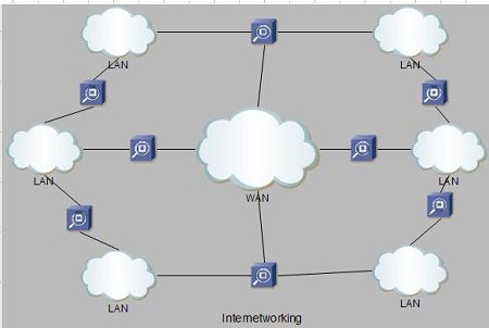
In modern practice, the interconnected computer networks or Internetworking use the Internet Protocol. Two architectural models are commonly used to describe the protocols and methods used in internetworking. The standard reference model forinternetworking is Open Systems Interconnection (OSI).
Internetworking is implemented in Layer 3 (Network Layer) of this model The most notable example of internetworking is the Internet (capitalized). There are three variants of internetwork or Internetworking, depending on who administers and who participates in them :
· Extranet
· Intranet
· Internet
· Extranet : An extranet is a network of internetwork or Internetworking that is limited in scope to a single organisation or entity but which also has limited connections to the networks of one or more other usually, but not necessarily, trusted organizations or entities .Technically, an extranet may also be categorized as a MAN, WAN, or other type of network, although, by definition, an extranet cannot consist of a single LAN; it must have at least one connection with an external network.
· Intranet : An intranet is a set of interconnected networks or Internetworking, using the Internet Protocol and uses IP-based tools such as web browsers and ftp tools, that is under the control of a single administrative entity. That administrative entity closes the intranet to the rest of the world, and allows only specific users. Most commonly, an intranet is the internal network of a company or other enterprise. A large intranet will typically have its own web server to provide users with browseable information.
· Internet : A specific Internetworking, consisting of a worldwide interconnection of governmental, academic, public, and private networks based upon the Advanced Research Projects Agency Network (ARPANET) developed by ARPA of the U.S.Department of Defense also home to the World Wide Web (WWW) and referred to as the 'Internet' with a capital 'I' to distinguish it from other generic internetworks. Participants in the Internet, or their service providers, use IP Addresses obtained from address registries that control assignments.
What is IPv4 -- Internet Protocol Version 4?
IPv4 (Internet Protocol Version 4) is the
fourth revision of the Internet Protocol (IP) used to to identify devices on anetwork through an addressing
system. The Internet Protocol is designed for use in interconnected systems of
packet-switched computer communication networks (see RFC:791).
IPv4 is the most widely deployed Internet protocol used to connect devices to
the Internet. IPv4 uses a 32-bitaddress scheme allowing for a total of 2^32 addresses (just over
4 billion addresses). With the growth of theInternet it is expected that the
number of unused IPv4 addresses will eventually run out because every device --
including computers, smartphones and game consoles -- that connects to the
Internet requires an address.
A new Internet addressing system Internet Protocol version 6 (IPv6) is being deployed to fulfill the need for more Internet addresses.
What is IPv6 -- Internet Protocol Version 6?
IPv6 (Internet Protocol Version 6) is also
called IPng (Internet Protocol next generation) and it
is the newest version of the Internet Protocol (IP) reviewed in the IETF standards committees to
replace the current version of IPv4 (Internet Protocol Version 4).
IPv6 is the successor to Internet Protocol Version 4 (IPv4). It was designed as
an evolutionary upgrade to the Internet Protocol and will, in fact, coexist
with the older IPv4 for some time. IPv6 is designed to allow the Internet to
grow steadily, both in terms of the number of hosts connected and the total
amount of data traffic transmitted.
IPv6 is often referred to as the "next
generation" Internet standard and has been under
development now since the mid-1990s. IPv6 was born out of concern that the
demand for IP addresses would exceed the available supply.
UNIT 5
Authentication is any process by which a system verifies the identity of a User who wishes to access it. Since Access Control is normally based on the identity of the User who requests access to a resource,Authentication is essential to effective Security.


Comments
Post a Comment